
Access Agilent eNewsletter, August 2013
>> Update My Profile | Subscribe to Access Agilent | Article Directory

Gain deeper insights into thin film response: overcome spectral oscillations with the Cary Universal Measurement Accessory
By Robert Frances
Agilent Senior Optical Engineer
and Travis Burt
Agilent Product Marketing Manager Cary UV-Vis-NIR
Designers and manufacturers of high quality multilayer optical coatings require reliable methods to measure optical constants of thin film materials with good accuracy. They typically use UV-visible-IR spectrophotometry to acquire normal and quasi-normal transmittance (T) and reflectance (R) spectra of a sample. The Agilent Cary 5000 UV-Vis-NIR spectrophotometer has a new accessory that improves data accuracy and provides more reliable sample characterization.
You get valuable information about data accuracy by calculating the total losses (TL) of the thin film sample using TL(λ) = 100%−R(λ)−T(λ). Typically, in the spectral range where the substrate and the thin film are nonabsorbing and nonscattering, you expect zero total losses, whereas with absorbing films, TL(λ) decreases with increasing λ.
Accessory overcomes source of error
When you analyze total losses spectra, you often observe oscillations, which may produce doubt about the quality of the data. One cause of oscillations arises from slight thickness nonuniformity of the thin film sample. However, this source of error can be small when compared with variations in angle of incidence (AOI) between T and R measurements. You can eliminate AOI error by use of the Agilent Universal Measurement Accessory (UMA) fitted to an Agilent Cary 5000 UV-Vis-NIR spectrophotometer. The UMA is a highly automated variable angle absolute specular reflectance and transmittance system that acquires T and R data without moving the sample.
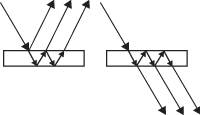
Figure 1. Schematic of the Agilent UMA, an accessory capable of front and back surface reflection (left) and direct and inter-reflected transmission (right).
More accurate, rapid, and complete optical characterization
We recently demonstrated how an Agilent Cary 5000 UV-Vis-NIR spectrophotometer equipped with an Agilent UMA provides new insights into thin film characterization. The UMA works as indicated in Figure 1, and uses the same spot on the sample for both T and R measurements. This multiple measurement mode capability of the UMA results in more accurate, rapid, and complete optical characterization of thin films.
Results provide new insights
Traditionally, reflectance and transmittance measurements have been performed using spectrophotometers fitted with different attachments. In practice, different areas of the sample surface may be tested. If the deposition process produces a film with a nonuniform thickness, it is reasonable to expect that reflectance and transmittance measurements were affected.
With the development of the UMA, it is now possible to measure T and R at the same sample point, overcoming one source of oscillations in the results. In a recent study, we used an Agilent Cary 5000 double beam UV-Vis-NIR spectrophotometer equipped with a new UMA to acquire transmittance data for s-polarized light at 7° and 10°, and s-polarized reflectance data at 10°. We measured a sample of Ta2O5 film of 292 nm thickness. To verify the capabilities of the new UMA, we reanalyzed the same sample a few months later with a second UMA unit and different sample mounts.
 Enlarge
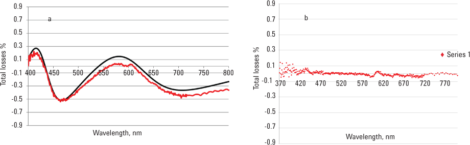
Figure 2. Comparison of a) TL(s)(λ) = 100%−T(s)(7°, λ)− R(s)(10°, λ) calculated from experimental data and TL(s)AOI(λ) calculated by theoretical equation[1]. b) Total losses TL(s)(λ) = 100%−T(s)(7°, λ)− R(s)(7°, λ) calculated from experimental data.
In the first experiment, we considered total losses calculated on the basis of T and R measurements taken at different AOIs using the first UMA unit according to: TL(s)(λ) = 100%−T(s)(7°, λ)−R(s)(10°, λ). The experimental total losses are plotted in Figure 2a (red line). Oscillations of approximately 0.4% magnitude are clearly observed. The solid curve (black line) in Figure 2a presents a theoretical approximation of total losses, which shows good agreement with the experimental results. This agreement confirms that the oscillations are due only to the difference in AOI, and the effect of thickness nonuniformity does not contribute to total losses spectral behavior.
In Figure 2b, we also show experimental total losses, calculated from T and R measurements taken at equal AOI: TL(s)(λ) = 100%−T(s)(7°, λ)−R(s)(7°, λ). The absence of any oscillations further confirms that thickness nonuniformity does not affect total losses when you acquire T and R measurements at the same sample point.
In the second experiment, which took place four months later, we acquired T and R data from the original sample on a new sample mount, using a different UMA unit coupled to the Cary 5000 spectrophotometer. The results were indistinguishable, as shown in Agilent Application Note 5991-2111EN.
Achieve better data
These results demonstrate that the residual oscillations observed after eliminating AOI variations are minimal and are in full agreement with the theoretical values. The findings confirm that the effect of thickness nonuniformity does not contribute to total losses spectral behavior when you use an instrument that is capable of T and R measurement at the same point of the sample. The latest Agilent multiangle spectral photometry provides researchers with more accurate spectroscopic information for the characterization of thin films.
If you need to analyze thickness of thin films, read the full Application Note 5991-2111EN, or see the more detailed account of this work in Optics Express[1]. Then learn how the Agilent Cary 5000 UV-Vis-NIR with the UMA delivers the same measurement flexibility and productivity as the Agilent Cary 7000 UMS. Watch this video to learn more.
Reference
- T. V. Amotchkina, M. K. Trubetskov, A. V. Tikhonravov, V. Janicki, J. Sancho-Parramon, O. Razskazovskaya, and V. Pervak, “Oscillations in spectral behavior of total losses (1−R−T) in thin dielectric films,” Optics Express 16129, 2 July 2012 / Vol. 20, No.14.
>> Update My Profile | Subscribe to Access Agilent | Article Directory
Figure 2.
Comparison of a) TL(s)(λ) = 100%−T(s)(7°, λ)− R(s)(10°, λ) calculated from experimental data and TL(s)AOI(λ) calculated by theoretical equation[1]. b) Total losses TL(s)(λ) = 100%−T(s)(7°, λ)− R(s)(7°, λ) calculated from experimental data.